|
|
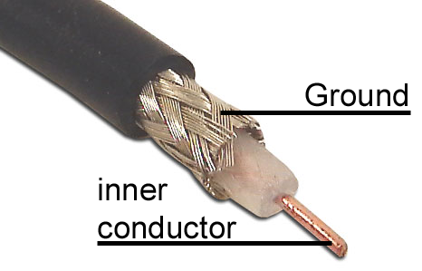
Everything depends on the quality of reception and the antenna is the most crucial part of the receiving system. It is not difficult to make a good antenna. Simply take a piece of wire six meters in length (20 ft) and connect it to the inner conductor of a coax cable. Then you take another piece of wire of the same length and connect it to the outer conductor of the coax cable. Now you string up the wires horizontally, with the coax hanging down in the center. Twelve meters (40 ft) or 18 meters (60 ft) are even better. A different wire length is not advisable for the reception of weather frequencies. A simple wire antenna is still a reference antenna for all other types of antennas. It is also common to use the backstay as an antenna. There are
various other compromises in case you are not able to string a
wire on your boat. Active antennas (amplified antennas) on boats
should be considered with caution. These antennas often amplify
interferences, not usable signals. We are offering a special
antenna, but would never claim that it is better than a
perfectly strung wire. Our antennas are simply better than all
other compromises, in cases where no decent wire antenna can be
erected. Most importantly, our antenna has been tested.
|
|
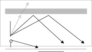
In contrast to VHF transmitting stations, short wave stations are mainly emitted into the ionosphere. The ionosphere layer reflects the signals back to earth. Therefore, it is possible to bridge large distances. This also means that a horizontally erected antenna offers the best reception. Direct reception of the radio station is only possible in relative proximity to the station antenna. The space that extends between direct and indirect reception areas is called skip zone. Here reception is either strongly inhibited or altogether impossible. That’s why in these cases a station on a different frequency should be selected. |
|
Tipp:
The further away you are from the received radio station the higher
the selected frequency should be. If, for example, you are in the German
area of the Baltic Sea, you will receive „Meteo Offenbach“ very well on
147,3kHz or 4553kH. If you are cruising in the Mediterranean you need to
tune your receiver to 13885kHz or 14467kHz.
The first test should always start
with a clear reception. If you don’t receive any usable signals you need
to improve the antenna. You can also wait for the reception to improve.
If you ignore this rule and try with a very weak signal, it will be
difficult to interpret the tuning elements and their function properly.
This is not to say that it won’t work at all. A knowledgeable individual
can still use a signal that seems unintelligible.
How am I supposed to adjust something that I can’t see or hear?
Once you have tuned a signal under good receiving conditions it can
still be decoded in less favourable circumstances. Since tuning and
parameters are saved in the frequency list, it can be reloaded in
exactly the same way later on. It is therefore not necessary to do the
tuning procedure again. This is where the decoder shows off its real
capabilities. It still decodes the signal because it does not “hear” the
interferences the same way you do with your ears. The electronic
components are able to filter through the unwanted parts of the signal
and pick out the essential ones. The loudspeaker on the other hand
simply reports what is being received. You will hear all kinds of things
which make it impossible for the human ear to ascertain whether there
still is a usable signal or not.
|
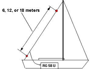
If you own a sailing boat the installation of an antenna is often very simple. In most cases you can use the backstay. It would be advantageous if the length of the isolated wire would be 6, 12 or 18 meters (20ft, 40ft or 60ft). Attach the inner conductor of the RG58U coax cable to the isolated wire part of the backstay and the outer conductor below the insulator. It is possible to use hose clips to attach the wires.
If there is no isolated wire piece in the backstay,
simply attach the inner conductor of the coax to the backstay and leave
the outer conductor as is. |
|
Tuning a signal – What is a usable signal?
In order to tune a signal it is
useful to be able to distinguish the tone signals of the various
operation modes.
There is a demo version on your CD. Open the demo, bring up the
frequency list and double-click on a frequency. The reception window
will open, as it will in the full version. You can now hear the signal
and also observe how MeteoCom processes the different tones, in a
weather fax map for example.
A signal is composed of tones with varying pitch, which are decoded
differently. The spacing between the first tone and the last is called
band width. All decodable signals have one thing in common: If you have
doubts that the signal is usable, it usually isn’t. Intelligible signals
are always discernable and stand out of the general noise and other
indefinable signals. Now we need to find out whether the signal is Morse
code, RTTY or FAX. The MeteoCom demo CD will help you with that.
Distinguishing the various RTTY signals, however, is a little bit more
complicated. „BordTerminal“ only analyzes Navtex and RTTY. There are
other forms of RTTY that are not picked up by the software even though
they are received by the radio. That’s why not every intelligible signal
is a usable signal in the context of maritime use. There are also
signals that are decoded properly but don’t make any sense. This could
be the case when you pick up a station from an Arab country that uses
different letters.
In order for the receiving program to work properly, you will need
assistance for correct tuning. The tuning assistant shows you where the
signal is and how much interference there is in its neighbourhood. There
are two different tuning assistants for RTTY: the frequency spectrum and
the X/Y tuning assistant. For Fax you only have the frequency spectrum.
If you control your radio using the software, all frequencies and
parameters are set perfectly. If the radio is stable there should be no
deviations and the program should be starting to decode right away. In
this case the tuning assistants are used merely to monitor the signal.
Receiving
Weather data
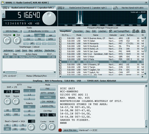
Receiving Radio Teletype (RTTY, Navtex, and Synop)
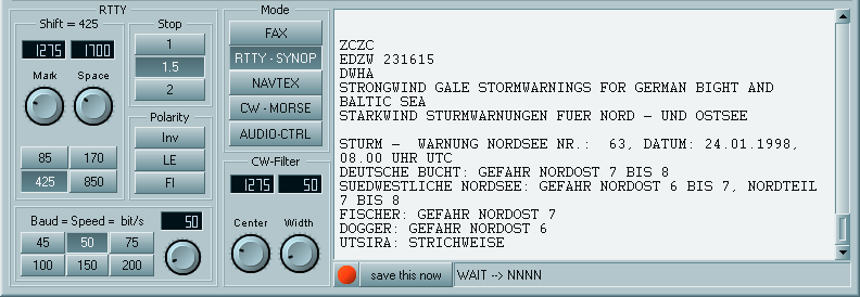
This is the RTTY surface. The text window displays the received message. Usually you will see the lowest row, meaning the one being received at that moment. If you want to read text that has scrolled off the screen and is no longer visible, click on the screen once. To reverse the process click onto the title bar above the text screen.
The MeteoCom 6 Demo version can be very helpful www.bonito.net/software/MC6DWebInstall.exe
Tuning RTTY
Usually, the tuning displays process the tones received by the radio in
such way that you can observe the way the radio tunes the signal. These
displays should help you understand how the tuning process works. As a
first test it may be useful to just turn the main tuning knob of your
radio to acquaint yourself with it. If, later on, you want to tune more
precisely, you need to use the „Receiver-Control“ because your radio
doesn’t report to MeteoCom when you tune your radio manually.
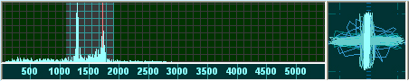
Frequency-Spectrum
This is a display showing all tone frequencies up to 2500 Hz from left
to right. The height corresponds with the volume (amplitude). The
amplitude is dependent upon the tone’s frequency. You should always try
to find the tone frequency yielding the strongest amplitude. There are
precise technical standards which specify at which tone a signal is
tuned properly. In real life, however, all this depends on the filters
used in your radio. The filter curves are not always the way they should
be. This means that the frequency list is always a theoretical tool and
not adapted to your specific radio.
|
|
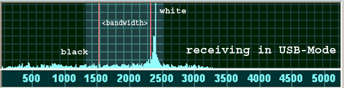
Make sure that both amplitudes are lined up exactly with the red lines. The spacing between the red lines corresponds with the band width (shift). The position on the scale is the tone’s frequency or pitch. The height shows the volume. This picture shows an RTTY signal with two different tones. One for “mark” and one for “space”. Both tones should be lined up with the vertical red lines. In case of a Fax signal, the bandwidth is usually greater, meaning that the two vertical lines are further apart and there is almost always only one bar at the red line on the right. The tuning process is explained in detail later on.
X/Y-Tuning Display (Tuning Cross)
|
The previous page showed an example for a RTTY-signal. The exact tuning possibilities are indicated here on the X/Y display. This tuning tool is used only for RTTY. Before using the tuning cross you should tune the signal with the frequency spectrum in such way that it lines up with the red vertical markers. Only after that should you try to use the tuning display and establish a cross shape. If this should not work initially, try playing with the bandwidth (page 25). If the bandwidth is correct the tuning display will show a cross. Now make sure that the lines forming the cross shape are straight, meaning aligned with the X-axis and Y-axis respectively. |
|


Tuning
|
If you can make out the
two signals clearly, then you can also read the bandwidth. |
 |
Operation Modes
Baudot:
This operation mode usually concerns common teletype text and is an
asynchronous mode. It is often used by press and weather services. SYNOP
messages are also broadcast in this mode.
Asynchronous means that the characters are marked with a start- and stop
bit, because they are transferred in an irregular way.
Sync. Baudot:
Baudot is an asynchronous mode. But it can be assumed that today’s
broadcasters use automatic machines for their transmissions. If the
reception of the signal is distorted the program presumes that the start
and stop bits are transmitted at a certain expectable position. It is
therefore likely that there really are start and stop bits at those
positions, even though they are not received properly. This logic
contributes to a low amount of reading errors. Should a message be
transmitted by a manually operated typewriter, this mode of operation
should not be selected.
Sitor-B:
This is a synchronous mode which is different from Baudot. But it does
use the same logic. This mode is much less affected by distortion. Sitor
is used for Navtex and is then always at 100 Baud.
Adjusting the Baud rate
The speed of the individual bits
in teletype is called Baud rate. Baud rate is derived from BAUDot. The
most frequently used Baud rates for normal Baudot are usually 50 Baud,
sometimes 75 Baud (Meteo Bracknel). On rare occasions you may encounter
100 Baud (Meteo Grengel). Navtex always uses 100 Baud, in mode Sitor-B,
however.
Shift + Marker frequency
The spacing of the two chirpy warbling sounds is the shift. The sounds
indicate the bit status of a RTTY bit. The shift is represented by two
red markers in the frequency analyzer. The marker frequency governs the
position of the markers. Meteo Offenbach 147.3 for example transmits at
an 85 Hz shift. Navtex uses a 170 Hz shift. Above 3 MHz Radio Offenbach
uses 425 Hz. Meteo Moscow and Meteo Roma both use 850 Hz.
Polarity
If reception is clear but the received characters don’t appear to make
sense, try switching the polarity to improve readability. Navtex for
example always transmits with an inverted polarity. But there may be
other reasons for an unreadable signal. It is possible that the message
text includes a character which causes the decoder to only read digits
and other data.
In this case you should try using the LE-mode to improve readability.
Activate FI only in a contrary situation when Synop 5-digit groups are
turned into groups of letters.
Stopbits
Baudot normally uses 1.5 stop bits. But it is possible to come across a
station using 2 stop bits. That is why there is an adjustment
possibility. Adjustment is not necessary in Sitor mode, since this mode
does not use stop bits.
| Information | Decoder |
| WeatherFax | Faximile |
| Audio | Audio |
| Synop and RTTY | Telex |
| Navtex | Navtex |
| Morsen | Morse |
| Satellite pictures | Images |
| Time Signals | Times |
Weather maps are broadcast using
„WeatherFax“. WeatherFax is the most frequently used way of broadcasting
processed weather data.
Normally there is no need for adjustments because all parameters are set
automatically when double clicking the frequency. If, however, you still
wish to make adjustments, you may use the following procedures:
IOC
There are several different image formats that can be used to receive
Fax. They are called modules. In our case module 576 is used most often,
sometimes module 288.
|
Modul 288: |
Small weather map module, approx. 800 pixels wide. |
|
Modul 352: |
Press images, approx. 1100 pixels. |
|
Modul 576: |
Large weather map module, approx. 1800 pixels. |
Drum Speed RPM
The drum rotation speed of a fax is denominated in revolutions per
minute (rpm). A normal weather fax uses 120 rpm. Weather maps from
Russia and Japan may come at varying speeds such as 60, 90 or 120 rpm.
Shift & Center frequency Fax Decoder
It is important to shift the tuning from high frequency tones to lower
frequency tones in order to avoid interference. This means you are
shifting the red markers in the frequency spectrum along the horizontal
scale.
Fax PreFilter
„Width“ is the spacing between the lowest and highest tone frequency of
a signal. That is the spacing between the two red markers in the
spectrum display. The filter should be the same width. Filter
adjustments that are narrower or wider may also improve the reception.
Start/Stop Frequencies
Start- and Stop frequencies are sounds played at the beginning and end
of an image. Normally there would be a 450 Hz tone for start and a 300
Hz tone for stop. After the start tone MeteoCom starts recording the fax
and saves it to the hard drive after the stop tone.
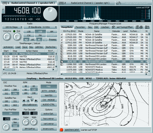
Spectrum- Analyzer
This is the display for tuning the tone frequency. In most cases a fax
signal USB shows more activity on the right side that degrades towards
the left end of the bandwidth (red marker).
In order to receive good, clear
images, the main signal activity bar should always be just in front of
the red marker. In case of distortion you can shift the IF to the left
or right, narrow the bandwidth or manipulate the filter.
Slant Correction
|
During the first test the image will come out skewed. In this case you can rectify the image by using the „<“ and „>“ buttons. Always use the button that points in the opposite direction of the skew (e.g. the right button in the case shown in the image below). You can use the 10x function to do large step correction or 1x for fine corrections. After completing the correction click on “Slant Calc” which will apply these values to all other modules and fax frequencies. |
|

|
|
Recommendation: If you are located in Europe, we recommend to use the „Northwood RN London“ broadcast station for skew correction. This station transmits a synchronizing signal which can be used as a marker (red circle on right hand side of the image above). |

Sie können weltweit die NAVTEX-Meldungen der Küstenfunkstellen auf den Frequenzen 490 kHz und 518 kHz in Küstennähe empfangen. Die Navtex Nachrichten finden Sie unter "Texte" "Navtex"
WICHTIG ! NICHT ZU VERWECHSELN!
NAVTEX Meldungen beinhalten z.B. Nautische Warnungen, Seenotmeldungen, Wetterberichte für 24 oder 48 Std., Sturmwarnungen.
Die Navtex Nachrichten werden mit
dem Fehler korrigierenden Funkfernschreibverfahren SITOR-B auf der
Frequenz 518 kHz in englischer Sprache, und in einigen Ländern auch auf
den Frequenzen 490 kHz sowie 4209,5 kHz in Landessprache verbreitet.
Japanische Sender übertragen Navtex-Meldungen in japanischer Sprache
auch auf der Frequenz 424 kHz.
|
|
| Web: www.bonito.net - www.hamradioshop.net - www.meteoserver.net - www.wetterinfoshop.de |